Sprung Arm
A rubber-band-loaded arm on a pivot, pulling cascadecascadeThe stringing architecture where all lift stages extend simultaneously at proportionally different speeds, so the load at the actuation point stays roughly constant.Click for the full glossary slides through a string — the 12993 RoboKings Aurum approach to counterspringingcounterspringingAdding a spring system that offsets a mechanism's gravity load, so the motor spends its torque on acceleration instead of on holding the mechanism's own weight.Click for the full glossary a linear lift. Also called a sprung linkagelinkageAn assembly of rigid links and pivots that transforms one motion or force into another — here, used to reshape a plain spring's force into a designed profile.Click for the full glossary.
A bundle of rubber bands loads a pivoting beam that hauls the lift's string. The beam's changing moment arm turns the bands' linear pull into a tension that stays nearly flat across a working window — a custom force level from cheap elastics, at the cost of geometry design and tuning.
Best for
Offseason projects and advanced teams who want a custom, tunable force level (matched to a cascade lift) from cheap rubber bands.
Poor fit for
Mid-season adoption, tight packaging, or teams without the CAD and iteration time to design and tune the beam geometry.
ComplexityHighComplexity: High, level 5 of 5. Custom geometry, pivots, and structure; the force profile is an engineered output, not a purchased one.
Custom geometry, pivots, and structure; the force profile is an engineered output, not a purchased one.
Force accuracyest.Potentially excellentForce accuracy: Potentially excellent, level 4 of 5. In theory the profile can be shaped to match gravity almost exactly; achieved accuracy depends entirely on execution and tuning.
In theory the profile can be shaped to match gravity almost exactly; achieved accuracy depends entirely on execution and tuning.
Packagingest.DemandingPackaging: Demanding, level 4 of 5. The beam sweeps through volume as the lift moves; the swept envelope must stay clear.
The beam sweeps through volume as the lift moves; the swept envelope must stay clear.
Tuning effortest.HighTuning effort: High, level 5 of 5. Geometry changes require remanufactured parts; expect multiple iterations to converge.
Geometry changes require remanufactured parts; expect multiple iterations to converge.
In-season riskest.HighIn-season risk: High, level 5 of 5. Long, hard-to-bound development time makes this a classic offseason experiment.
Long, hard-to-bound development time makes this a classic offseason experiment.
Click a metric to see why it’s rated that way. Ratings marked est. are editorial estimates awaiting test data.
Quick recommendation
Use this when
- You want a custom force level no COTS spring rating provides, from cheap rubber bands
- Your lift is cascade-strung, so the load is near-constant across the stroke
- You have offseason time to iterate on geometry and validate with measurements
- Structural mounting for the beam pivot and band anchor is available
Avoid this when
- It is competition season and the lift must work next week
- Packaging around the lift base is already tight — the beam sweeps volume
- Pivot slop or frame flex would corrupt the designed force profile
- Nobody on the team can own the beam geometry end-to-end
What the mechanism actually is
Forget catalogs for a moment. This counterspringcounterspringingAdding a spring system that offsets a mechanism's gravity load, so the motor spends its torque on acceleration instead of on holding the mechanism's own weight.Click for the full glossary is four parts:
- A rigid beam (a metal arm) that pivots about one fixed point near the lift base.
- A bundle of rubber bands anchored at one end to a fixed axle, and at the other end to a point on the beam — a distance r out from the beam's pivot. The bands are the spring.
- A string that runs from the beam, over a bearing/pulley, down to the linear slides.
- The cascadecascadeThe stringing architecture where all lift stages extend simultaneously at proportionally different speeds, so the load at the actuation point stays roughly constant.Click for the full glossary-strung slides themselves.
When the lift is driven down, the beam is rotated and the bands are stretched — energy goes in. When the motor eases off, the stretched bands pull the beam back, the beam hauls on the string, and the string lifts the slides. The bands are, in effect, holding most of the lift's weight so the motor only has to supply the difference.
Why "cascade" matters here
The slides are strung in cascadecascadeThe stringing architecture where all lift stages extend simultaneously at proportionally different speeds, so the load at the actuation point stays roughly constant.Click for the full glossary: every stagestageOne telescoping section of a lift. Each stage rides on the one below it; the counterspring must handle whichever stages are moving.Click for the full glossary is tied to the one before it, so they all extend together and the string at the actuation point sees a load that stays roughly constant over the whole stroke. (Contrast continuous stringing, where the effective load steps as stagesstageOne telescoping section of a lift. Each stage rides on the one below it; the counterspring must handle whichever stages are moving.Click for the full glossary hand off.)
That constant target is exactly what makes this arm practical. The design job is simply: keep the string tension roughly flat over the sweep, at the value that cancels the slides' weight. You are matching a flat line, not a staircase.
The physics, worked out
Put the beam pivot O at the origin. The bands anchor at a fixed point A a distance d to one side of the pivot. The bands attach to the beam at point P, a distance r from the pivot, and the beam sits at angle θ. So P = (r·cosθ, r·sinθ) and A = (−d, 0).
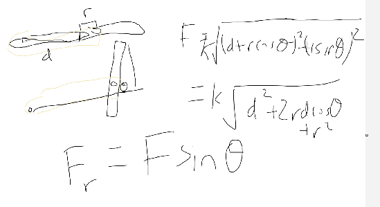
The original napkin derivation from the source discussion — the same result, reached by hand.
Step 1 — how long is the spring at angle θ? The band length is just the distance from A to P:
In plain terms: As the beam swings, the distance between the fixed anchor and the moving attachment point changes — so the bands stretch and their force grows. This is where the position dependence enters.
Assumes: Bands modeled as a linear spring · Anchor and pivot in one plane
Step 2 — how hard do the bands pull? Rubber bands only pull, and (over their working range) roughly follow Hooke's lawHooke's lawF = kx: an ordinary spring's force grows linearly with how far it is stretched. The reason bungee force rises with extension while a gravity load doesn't.Click for the full glossary from some unstretched length L₀:
In plain terms: k is the combined stiffness of all the band loops. Adding bands multiplies k; it does not change the shape of the curve.
Step 3 — turn that into a torque on the beam. Only the part of the band force that acts perpendicular to the beam twists it about the pivot. Working out the moment of F_s about O gives a strikingly clean result:
In plain terms: The d·r·sinθ / L factor is the spring's moment arm about the pivot. It vanishes at θ = 0° and θ = 180° (the band line passes through the pivot — no leverage) and is largest near θ = 90°.
Step 4 — the payoff. Heavily preloaded rubber bands behave close to a zero-free-length spring (force nearly proportional to total length, L₀ → 0). Substitute F_s = k·L and the length cancels:
In plain terms: R is the string's moment arm (the pulley/bearing radius). In this limit the tension delivered to the slides is a pure sine in the beam angle — set by geometry (d, r, R) and the number of bands (k).
| Symbol | Quantity | Unit | Notes |
|---|---|---|---|
| Beam angle | deg | Sweeps as the slides move | |
| Band mount radius | mm | Pivot → band attachment on the beam — the main leverage knob | |
| Pivot → anchor offset | mm | — | |
| String moment arm | mm | Effective pulley/bearing radius the string leaves on | |
| Combined band stiffness | N/m | ≈ (per-band stiffness) × (number of loops) | |
| Unstretched band length | mm | — |
How does the force behave — the questions this answers
Is the output force sinusoidal? Yes — the math genuinely lands on
T ∝ sinθ in the zero-free-length limit. It is a geometric sine (a
moment-armmoment armThe perpendicular distance from a pivot to a force's line of action. Changing it along travel is how a sprung arm shapes its force profile.Click for the full glossary effect), not a vibration. Real bands add an L₀ correction that
tilts the curve slightly.
Why is the lift only balanced over part of its travel? The match is only good over the window of θ you operate in. Run the beam through a sweep centered on θ = 90°, where sinθ ≈ 1 and changes slowly, and the tension is nearly flat — that is the "sweet spot." Push toward 0° or 180° and the tension collapses.
How does the force change as the beam angle changes? It rises with the beam toward 90° and falls past it, following sinθ. Because sinθ is flattest at its peak, a symmetric sweep about 90° gives the smallest ripple — which is exactly what you want against a constant cascadecascadeThe stringing architecture where all lift stages extend simultaneously at proportionally different speeds, so the load at the actuation point stays roughly constant.Click for the full glossary load.
Can moving the bands out or adding length reduce how many bands I need?
Yes, and the equation says how much. Output scales with d·r, so the torque
(and tension) grows linearly with r. Move the band mount twice as far
from the pivot and you roughly halve the number of bands for the same lift.
The trade: a larger r also stretches the bands more per degree of sweep, so
the tension varies more across the window — you buy fewer bands with more
ripple.
Continuous vs. cascade
The near-constant cascadecascadeThe stringing architecture where all lift stages extend simultaneously at proportionally different speeds, so the load at the actuation point stays roughly constant.Click for the full glossary load is the natural fit. Center the beam's sweep on θ = 90° and the sine is flat enough to hold the lift across its whole stroke with a single band bundle.
- Arrangement: beam pivoted at the base, bands from a fixed axle to a point on the beam, string over a bearing to the first stagestageOne telescoping section of a lift. Each stage rides on the one below it; the counterspring must handle whichever stages are moving.Click for the full glossary.
- Force profileforce profileHow a spring system's output force varies across the lift's travel — linear for bungee, flat for constant-force, stepped or shaped for others. Matching it to the gravity load is the whole game.Click for the full glossary: near-constant over the working window.
- Advantage: all-custom force level — dial it in with band count and mount radius, no catalog quantization.
- Limitation: the beam sweeps real volume, and the match degrades if the window drifts away from 90°.
A continuouscontinuousThe stringing architecture where lift stages extend one after another, so the moving mass — and the gravity load — increases in steps as the lift rises.Click for the full glossary lift's stepped load is a harder target: you would want the tension to jump at stagestageOne telescoping section of a lift. Each stage rides on the one below it; the counterspring must handle whichever stages are moving.Click for the full glossary transitions, and a smooth sine can only ramp. Possible, but you are fighting the mechanism's natural shape — a cam-driven linkagelinkageAn assembly of rigid links and pivots that transforms one motion or force into another — here, used to reshape a plain spring's force into a designed profile.Click for the full glossary is the better tool if you truly need to match a staircase.
Interactive: sweep the arm, watch the force
Drag the schematic to rotate the beam and watch the bands stretch and the
tension change. The graph plots string tension across the whole 0–180° swing;
the shaded band is your working window. Tune r, d, band count, and the
window to flatten the curve onto the target load.
Sprung-Arm Force Explorer
Interactive statics model & geometry tuner
1. Geometry & Motion Schematic
2. String Tension Profile ($T$ vs $\theta$)
Shaded = Working Window [68°–112°]Flattest near θ = 90° (sine peak). Match target load across window.
Mean Tension in Window
45.3 N
≈ 10.2 lbf
Tension Ripple
18%
Range: 39–47 N
Assist vs. Target Load
101%
Target: 45 N
Band Loops Needed
≈ 6 loops
Current: 6 loops (540 N/m)
Rubber bands are modeled as linear springs with rest length $L_0$. Real latex exhibits progressive stiffness near full stretch and thermal drift. Use this explorer for geometry design, then fine-tune with a scale on hardware.
Design and sizing
A realistic loop for this arm:
- Measure the target load. Pull the assembled cascadecascadeThe stringing architecture where all lift stages extend simultaneously at proportionally different speeds, so the load at the actuation point stays roughly constant.Click for the full glossary slides through
travel with a luggage scale; that near-constant number is your
Ttarget. - Pick a working window around 90°. Keep the beam a few degrees clear of both 0° and 180° — near the ends the moment armmoment armThe perpendicular distance from a pivot to a force's line of action. Changing it along travel is how a sprung arm shapes its force profile.Click for the full glossary collapses and the force gets twitchy (the source notes it "gets weird" past ~175°).
- Set leverage before band count. Choose
r,d, and the string radiusRso a reasonable number of bands hits the target — leverage is free, bands are consumable and drift. - Add bands to reach the force. Total stiffness scales with loop count; this is your fine adjustment.
- Check the ripple. If the tension varies too much across the window,
narrow the window (shorter stroke on the beam), reduce
r, or move the window to sit more symmetrically on 90°.
Worked example: Sizing an arm to hold a ~45 N cascade lift
Cascade slides that weigh in at ~45 N at the string. Beam swings 50°→130° over the stroke. Band mount r = 60 mm, anchor offset d = 40 mm, string radius R = 20 mm.
Near θ = 90° the zero-free-length estimate is T ≈ k·d·r / R (sinθ ≈ 1).
Solving for the stiffness you need at the peak: k ≈ T·R / (d·r) = 45 × 0.020 / (0.040 × 0.060) ≈ 375 N/m. If each band loop contributes
~90 N/m of effective stiffness in this geometry, that is roughly 4 loops
at the flat top — but because the real window dips below the peak toward its
edges, you add loops until the window mean hits 45 N, not just the peak.
Push the mount out to r = 90 mm and the same load needs about a third fewer
loops. Numbers are illustrative — the explorer above lets you retune them,
and the built arm gets the final say on a scale.
CAD, manufacturing, and assembly
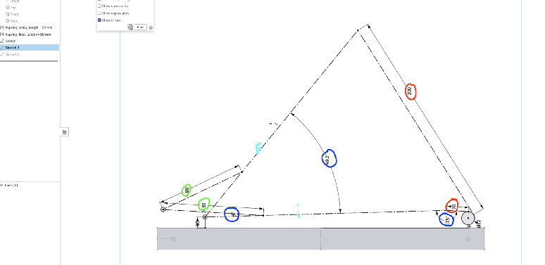
The source geometry sketch. Green = band lengths; light blue = start/end positions of the bands and linkagelinkageAn assembly of rigid links and pivots that transforms one motion or force into another — here, used to reshape a plain spring's force into a designed profile.Click for the full glossary; the 20 mm is the string offset to the bearing and 200 = 180 mm stroke + 20; the ~49–175° figures are the beam's angular limits before the sketch degenerates.
- The pivot is the product. Slop at the beam pivot is multiplied straight into tension noise — use a bearing or a real bushing, not a bolt in a hole.
- Anchor the bands properly. Bands fail at their hooks; run them over a smooth axle or a captive spoolspoolThe cylinder a spring coil or string winds onto. Constant-force springs mount on free-spinning spools; the lift's drive string winds on a driven spool.Click for the full glossary, never a sharp screw thread.
- Reserve the swept volume. Model the beam's full arc as a solid keep-out in the assembly; nothing else may live there.
- Make the mount radius adjustable. Slotted holes or a few mounting
positions for the band attachment let you retune
ron the robot — the single most useful adjustment.
Testing and validation
- Profile measurement: motor disconnected, pull the lift through travel with a luggage scale in both directions; plot force vs. height against the flat target. This is the report card for your window choice.
- Release test: does the lift float, climb, or settle when let go at
several heights? Climbing = over-sprung (drop bands); settling =
under-sprung (add bands or push
rout). - Slop audit: wiggle the pivot and band anchors before and after cycle testing; log any growth in free play.
- Band fatigue watch: measure tension fresh, then after a full match's worth of cycles and after heat — latex softens, so re-check between events.
- Re-measure after every tune: any change to
r, the window, or band count reshapes the whole curve.
Real-world examples
12993 RoboKings Aurum
Sprung ArmCENTERSTAGE · cascade stringing
Cascade slides countersprung by a rubber-band-loaded pivoting arm pulling a string over a bearing. Source for this page; measured force profile and band counts still to be documented.
Placeholder card — a real, verified team example belongs here. Contributions welcome.
Common failure modes
Window drifts off 90° — tension sags at one endMedium severity
- Cause
- Beam sweep centered too low or too high, so one edge of the stroke rides down the steep part of the sine.
- Symptoms
- Lift floats at mid-height but settles (or climbs) near one end of travel.
- Prevention
- Center the working window on θ = 90° in CAD; keep both ends clear of 0°/180°.
- Fix
- Re-index the beam's rest angle or shorten its sweep so it straddles 90°.
Band bundle fatigues and force fadesMedium severity
- Cause
- Latex creep and heat soften the bands over a match or a season.
- Symptoms
- A lift tuned to float now needs more motor to hold; float point drops over time.
- Prevention
- Over-provision slightly; log tension between events; treat bands as consumables.
- Fix
- Replace the bundle and re-measure; re-tune band count.
Pivot slop corrupts the profileHigh severity
- Cause
- A loose beam pivot; play is multiplied by the leverage into tension noise.
- Symptoms
- Audible knock at direction changes; float point wanders match to match.
- Prevention
- Bearing/bushing at the pivot; slop audit in the maintenance routine.
- Fix
- Replace the pivot; re-tune afterward.
Beam sweeps into another mechanismMedium severity
- Cause
- Swept arc not reserved in CAD, or a late part added into it.
- Symptoms
- Intermittent jams at specific lift heights.
- Prevention
- Model the sweep as a solid keep-out in the assembly.
- Fix
- Re-route the other mechanism — the beam's arc is fixed by its geometry.
How this compares
A bungee routed along the slides is the shortcut version of this same idea — an elastic pulling the lift directly. The arm adds a pivot so geometry, not just pretension, sets the profile: flatter force, but a real mechanism to build.
GuideConstant-force springs buy a flat profile straight from a catalog with almost no design. Choose the arm when you want a custom force level from cheap rubber bands, already have the packaging for a beam, or are doing this as an offseason build.
GuideConstant torque delivers one flat level from a steel spring at the winch. The arm delivers a tunable level from bands at the base — cheaper and adjustable, but with more to design and a force that ripples across the sweep.
GuideFor the full matrix, force-curve overlay, and decision summary, see Compare Methods.
References
- 12993 RoboKings Aurum — Behind the Bot (CENTERSTAGE)Robot example
Primary source: the rubber-band-loaded arm counterspring on cascade slides. Clip starts at 11:31.
- Source design discussion + Onshape geometry sketchEngineering source
The physics thread and napkin derivation this page is built from; images reproduced above.
- Zero-free-length spring balancing (standard mechanism-design result)Engineering source
The T ∝ sinθ result is the classic gravity-balancer statics, reached here with rubber bands and a beam.